- Home
- Machinery Directive
- History of the Machinery Directive 2006/42/EC
- Machinery directive 2006/42/EC
- Whereas of machinery directive 2006/42/EC
- Articles of machinery directive 2006/42/EC
- Article 1 of machinery directive 2006/42/EC - Scope
- Article 2 of machinery directive 2006/42/EC - Definitions
- Article 3 : Specific Directives of machinery directive 2006/42/EC
- Article 4 : Market surveillance of machinery directive 2006/42/EC
- Article 5 : Placing on the market and putting into service - machinery directive 2006/42/EC
- Article 6 : Freedom of movement - machinery directive 2006/42/EC
- Article 7 : Presumption of conformity and harmonised standards - machinery directive 2006/42/EC
- Article 8 : Specific measures - machinery directive 2006/42/EC
- Article 9 : Specific measures to deal with potentially hazardous machinery - machinery directive 2006/42/EC
- Article 10 : Procedure for disputing a harmonised standard - machinery directive 2006/42/EC
- Article 11 : Safeguard clause - machinery directive 2006/42/EC
- Article 12 : Procedures for assessing the conformity of machinery - machinery directive 2006/42/EC
- Article 13 : Procedure for partly completed machinery - 2006/42/EC
- Article 14 : Notified bodies - machinery directive 2006/42/EC
- Article 15 : Installation and use of machinery - machinery directive 2006/42/EC
- Article 16 : CE marking - machinery directive 2006/42/EC
- Article 17 : Non-conformity of marking - machinery directive 2006/42/EC
- Article 18 : Confidentiality - machinery directive 2006/42/EC
- Article 19 : Cooperation between Member States - machinery directive 2006/42/EC
- Article 20 : Legal remedies - machinery directive 2006/42/EC
- Article 21 : Dissemination of information - machinery directive 2006/42/EC
- Article 22 : Committee - machinery directive 2006/42/EC
- Article 23 : Penalties - machinery directive 2006/42/EC
- Article 24 : Amendment of Directive 95/16/EC - machinery directive 2006/42/EC
- Article 25 : Repeal - machinery directive 2006/42/EC
- Article 26 : Transposition - machinery directive 2006/42/EC
- Article 27 : Derogation - machinery directive 2006/42/EC
- Article 28 : Entry into force - machinery directive 2006/42/EC
- Article 29 : Addressees - machinery directive 2006/42/EC
- ANNEX I of machinery directive 2006/42/EC - Summary
- GENERAL PRINCIPLES of annex 1 of machinery directive 2006/42/EC
- 1 ESSENTIAL HEALTH AND SAFETY REQUIREMENTS of annex 1 - definitions - machinery directive 2006/42/EC
- Article 1.1.2. Principles of safety integration of annex 1 machinery directive 2006/42/EC
- Article 1.1.3. Materials and products annex 1 machinery directive 2006/42/EC
- Article 1.1.4. Lighting - annex 1 machinery directive 2006/42/EC
- Article 1.1.5. Design of machinery to facilitate its handling - annex 1 machinery directive 2006/42/EC
- Article 1.1.6. Ergonomics - annex 1 machinery directive 2006/42/EC
- Article 1.1.7. Operating positions - annex 1 machinery directive 2006/42/EC
- Article 1.1.8. Seating - annex 1 machinery directive 2006/42/EC
- Article 1.2.1. Safety and reliability of control systems - annex 1 of machinery directive 2006/42/EC
- Article 1.2.2. Control devices - annex 1 of machinery directive 2006/42/EC
- Article 1.2.3. Starting - annex 1 of machinery directive 2006/42/EC
- Article 1.2.4. Stopping - annex 1 of machinery directive 2006/42/EC
- Article 1.2.4.4. Assembly of machinery - Annex 1 of machinery directive 2006/42/EC
- Article 1.2.5. Selection of control or operating modes - annex 1 of machinery directive 2006/42/EC
- Article 1.2.6. Failure of the power supply - annex 1 of machinery directive 2006/42/EC
- Article 1.3. PROTECTION AGAINST MECHANICAL HAZARDS - annex 1 of machinery directive 2006/42/EC
- Article 1.4. REQUIRED CHARACTERISTICS OF GUARDS AND PROTECTIVE DEVICES - annex 1 of machinery directive 2006/42/EC
- Article 1.5. RISKS DUE TO OTHER HAZARDS - annex 1 of machinery directive 2006/42/EC
- Article 1.6. MAINTENANCE - annex 1 of machinery directive 2006/42/EC
- Article 1.7. INFORMATION - annex 1 of machinery directive 2006/42/EC
- Article 2. SUPPLEMENTARY ESSENTIAL HEALTH AND SAFETY REQUIREMENTS - annex 1 machinery directive 2006/42/EC
- Article 3. SUPPLEMENTARY ESSENTIAL HEALTH TO THE MOBILITY OF MACHINERY - annex 1 machinery directive 2006/42/EC
- Article 4. SUPPLEMENTARY REQUIREMENTS TO OFFSET HAZARDS DUE TO LIFTING OPERATIONS of machinery directive 2006/42/EC
- Article 5. SUPPLEMENTARY ESSENTIAL HEALTH AND SAFETY REQUIREMENTS FOR UNDERGROUND WORK of machinery directive 2006/42/EC
- Article 6. SUPPLEMENTARY REQUIREMENTS - HAZARDS DUE TO THE LIFTING OF PERSONS of machinery directive 2006/42/EC
- Annex II : Declarations of CONFORMITY OF THE MACHINERY, DECLARATION OF INCORPORATION - machinery directive 2006/42/EC
- Annex III of machinery directive 2006/42/EC - CE marking
- Annex IV of machinery directive 2006/42/EC
- Annex V of machinery directive 2006/42/EC
- Annex VI of machinery directive 2006/42/EC
- Annex VII - Technical file for machinery - machinery directive 2006/42/EC
- Annex VIII - Assessment of conformity of machinery directive 2006/42/EC
- Annex IX of machinery directive 2006/42/EC - EC type-examination
- Annex X of machinery directive 2006/42/EC - Full quality assurance
- Annex XI of machinery directive 2006/42/EC - Minimum criteria for the notification of bodies
- Annex XII of machinery directive 2006/42/EC - Correlation table between machinery directive 2006/42/CE and MD 1998/37/CE
- Machinery directive 1998/37/EC
- considerings of machinery directive 1998/37/CE
- articles of 1998/37/EC machinery directive
- Annex I of 1998/37/CE machinery directive
- Annex II of 1998/37/EC machinery directive
- Annex III of machinery directive 1998/37/CE
- Annex IV of machine directive 1998/37/EC
- Annex V of machines directive 1998/37/CE
- Annex VI of machines directive 1998/37/EC
- Annex VII of machines directive 1998/37/EC
- Annex VIII of 1998/37/CE machine directive
- Annex IX of machinery directive 1998/37/CE
- Machinery directive 1989/392/EC
- whereas of machinery directive machines 1989/392/EEC
- articles of machinery directive 1989/392/EEC
- Annex I of machinery directive 1989/392/EEC
- Annex II of machine directive 1989/392/EEC
- Annex III of machinery directive 1989/392/EEC
- Annex IV of machinery directive 1989/392/EEC
- Annex V of machinery directive 1989/392/EEC
- Annex VI of machine directive 1989/392/EEC
- Annexe VII of machinery directive 1989/392/EEC
- Amendments of 1989/392/EEC directive
- ATEX directives
- ATEX 94/9/EC directive
- Whereas of ATEX 94/9/CE directive
- Articles of ATEX 94/9/CE directive
- article 1 ATEX 94/9/EC directive
- article 2 ATEX 94/9/EC directive
- article 3 ATEX 94/9/EC directive
- article 4 : ATEX 94/9/EC directive
- article 5 : ATEX 94/9/EC directive
- article 6 : ATEX 94/9/EC directive
- article 7 : ATEX 94/9/EC directive
- article 8 ATEX 94/9/EC directive
- article 9 : ATEX 94/9/EC directive
- article 10 : ATEX 94/9/EC directive
- article 11 : ATEX 94/9/EC directive
- article 12 : ATEX 94/9/EC directive
- article 13 : ATEX 94/9/EC directive
- article 14 : ATEX 94/9/EC directive
- article 15 : ATEX 94/9/EC directive
- article 16 : ATEX 94/9/EC directive
- ANNEX I of ATEX 94/9/EC directive : CRITERIA DETERMINING THE CLASSIFICATION OF EQUIPMENT-GROUPS INTO CATEGORIES
- ANNEX II of ATEX 94/9/EC : directive ESSENTIAL HEALTH AND SAFETY REQUIREMENTS -EHSR
- ANNEX III of ATEX 94/9/EC directive : MODULE EC-TYPE EXAMINATION
- ANNEX IV of ATEX 94/9/EC directive : MODULE PRODUCTION QUALITY ASSURANCE
- ANNEX V of ATEX 94/9/EC directive : MODULE PRODUCT VERIFICATION
- ANNEX VI of ATEX 94/9/EC directive : MODULE CONFORMITY TO TYPE
- ANNEX VII of ATEX 94/9/EC directive : MODULE PRODUCT QUALITY ASSURANCE
- ANNEX VIII of ATEX 94/9/EC directive : MODULE INTERNAL CONTROL OF PRODUCTION
- ANNEX IX of ATEX 94/9/EC directive : MODULE UNIT VERIFICATION
- ANNEX X of ATEX 94/9/EC directive : CE Marking - Content of the EC declaration of conformity
- ANNEX XI of ATEX 94/9/EC directive: NOTIFICATION OF BODIES
- ATEX 99/92/EC Directive
- ATEX DIRECTIVE 2014/34/UE
- whereas of 2014/34/UE ATEX directive
- Articles of ATEX 2014/34/UE directive
- Annex 1 of ATEX 2014/34/UE directive
- Annex 2 of the ATEX 2014/34/UE directive
- Annex 3 of ATEX 2014/34/UE directive
- Annex 4 of ATEX 2014/34/UE directive
- Annex 5 of ATEX 2014/34/UE directive
- Annex 6 of ATEX 2014/34/UE directive
- Annex 7 of ATEX 94/9/EC directive
- Annex 8 of the ATEX 2014/34/UE directive
- Annex 9 of the ATEX 2014/34/UE directive
- Annex 10 of ATEX 2014/34/UE directive
- Annex 11 of ATEX 2014/34/UE directive
- Annex 12 of the ATEX 2014/34/UE directive
- Audits in Ex field - EN 13980, OD 005 and EN ISO/CEI 80079-34
- New ATEX directive
- RASE european project
- ATEX 94/9/EC directive
- IECEX
- Standardization & European Regulation
- Safety of machines : Standardization and European regulations
- European regulation for machines - standardization for machines - harmonized standards
- Standardization in machinery
- EN ISO 12100 - Décembre 2010
- EN ISO 12100-1 - January 2004
- EN ISO 12100-1:2003/A1
- EN ISO 12100-2 November 2003
- EN ISO 12100-2:2003/A1
- EN ISO 14121-1 September 2007
- ISO/TR 14121-2 - 2007
- EN 50205:2002 standard - Relays with forcibly guided (mechanically linked) contacts
- ISO 11161:2007
- ISO 13849-1:2006
- ISO 13849-2:2012
- ISO 13850:2006 - Safety of machinery -- Emergency stop -- Principles for design
- ISO 13851:2002 - Safety of machinery -- Two-hand control devices -- Functional aspects and design principles
- ISO 13854:1996 Safety of machinery - Minimum gaps to avoid crushing of parts of the human body
- ISO 13855:2010 - Safety of machinery -- Positioning of safeguards with respect to the approach speeds of parts of the human body
- ISO 13856-1:2013 Safety of machinery -- Pressure-sensitive protective devices -- Part 1: General principles
- ISO 13856-2:2013 - Safety of machinery -- Pressure-sensitive protective devices -- Part 2: General principles for design testing
- ISO 13856-3:2013 Safety of machinery -- Pressure-sensitive protective devices - Part 3: General principles for design
- ISO 13857:2008 Safety of machinery -- Safety distances to prevent hazard zones
- ISO 14118:2000 - Safety of machinery -- Prevention of unexpected start-up
- ISO 14119:2013- Interlocking devices associated with guards
- ISO 14120:2002 - Guards -- General requirements for the design and construction
- ISO 14122-1:2001 - Permanent means of access to machinery
- ISO 14122-2:2001 - Permanent means of access to machinery
- ISO 14122-4:2004 - Permanent means of access to machinery
- ISO 14123-1:1998 - Reduction of risks to health from hazardous substances emitted by machinery
- ISO 14123-2:1998 - Reduction of risks to health from hazardous substances emitted by machinery
- ISO 14159:2002 - Hygiene requirements for the design of machinery
- ISO 19353:2005 -- Fire prevention and protection
- ISO/AWI 17305 - Safety of machinery - Safety functions of control systems
- ISO/DTR 22100-2 - Safety of machinery -- Part 2: How ISO 12100 relates to ISO 13849-1
- ISO/TR 14121-2:2012 - Risk assessment - Part 2: Practical guidance
- ISO/TR 18569:2004 - Guidelines for the understanding and use of safety of machinery standards
- ISO/TR 23849:2010 - Guidance on the application of ISO 13849-1 and IEC 62061 in the design of safety-related control systems
- STABILITY DATES FOR Machinery STANDARDS
- harmonized standards list - machinery-directive 2006/42/CE
- Publication of harmonised standards for machinery directive 2006/42/EC - 9.3.2018
- Harmonized standard list - machinery directive 2006/42/EC - 9.6.2017
- Harmonized standards for machinery - OJ C 2016/C173/01 of 15/05/2016
- Harmonized standards for machinery -OJ C 2016/C14/102 of 15/01/2016
- Harmonized standards for machinery - corrigendum OJ C 2015/C 087/03 of 13/03/2015
- harmonized standards for machinery - OJ C 2015/C 054/01 of 13/02/2015
- Application guide for machinery directive 2006/42/EC
- Guide to application of the machinery directive 2006/42/CE - July 2017
- Guide to application of the Machinery Directive 2006/42/EC - second edition June 2010
- Guide to application of machinery directive - 1-2 : The citations
- Guide to application of machinery directive - § 3 to § 31 The Recitals
- Guide to application of machinery directive - § 32 to § 156 - The Articles
- Guide to application of machinery directive - § 157 to § 381 - Annex I
- Guide to application of machinery directive - § 382 to § 386 - ANNEX II Declarations
- Guide to application of machinery directive - § 387 - ANNEX III CE marking
- recommendation for use - machinery directive 2006/42/EC
- Notified bodies under the machinery directive 2006/42/CE
- Safety of Ex, ATEX and IECEx equipments : Standardization
- Standardization in Ex Field
- The transposition of the ATEX 94/9/EC Directive to the 2014/34/EU directive
- harmonized standards list - ATEX directive 2014/34/EU
- Harmonized standard list for ATEX 2014/34/UE - 12-10-2018
- Harmonized standard list for ATEX 2014/34/UE - 15.6.2018
- Harmonized standard list for ATEX 2014/34/UE - 12-07-2019
- Harmonized standard list for ATEX 2014/34/UE - 9.6.2017
- Harmonized standards list ATEX 2014/34/UE directive - OJ C 126 - 08/04/2016
- Guide to application of the ATEX Directive 2014/34/EU
- application guide of 2014/34/EU directive - preambule, citations and recitals
- Guide to application of the ATEX 2014/34/UE directive - THE ARTICLES OF THE ATEX DIRECTIVE
- Guide to application of the ATEX 2014/34/UE directive - ANNEX I CLASSIFICATION INTO CATEGORIES
- Guide to application of the ATEX 2014/34/UE directive - ANNEX II ESSENTIAL HEALTH AND SAFETY REQUIREMENTS
- Guide to application of the ATEX 2014/34/UE directive - ANNEX III MODULE B: EU-TYPE EXAMINATION
- Guide to application of the ATEX 2014/34/UE directive - ANNEX IV MODULE D: CONFORMITY TO TYPE
- Guide to application of machinery directive - § 388 - ANNEX IV machinery and mandatory certification
- Guide to application of the ATEX 2014/34/UE directive - ANNEX V MODULE F: CONFORMITY TO TYPE
- Alignment of ten technical harmonisation directives - Decision No 768/2008/EC
- ATEX 94/9/EC directive documents
- ATEX 94/9/EC guidelines
- ATEX 94/9/EC guidelines 4th edition
- 1 INTRODUCTION of ATEX 94/9/EC guidelines 4th edition
- 2 OBJECTIVE OF THE ATEX DIRECTIVE 94/9/EC - ATEX 94/9/EC guidelines 4th edition
- 3 GENERAL CONCEPTS of ATEX 94/9/EC directive ATEX 94/9/EC guidelines 4th edition
- 4 IN WHICH CASES DOES DIRECTIVE 94/9/EC APPLY - ATEX 94/9/EC guidelines 4th edition
- 5 EQUIPMENT NOT IN THE SCOPE OF DIRECTIVE 94/9/EC - ATEX 94/9/EC guidelines 4th edition
- 6 APPLICATION OF DIRECTIVE 94/9/EC ALONGSIDE OTHERS THAT MAY APPLY - ATEX 94/9/EC guidelines 4th edition
- 7 USED, REPAIRED OR MODIFIED PRODUCTS AND SPARE PARTS - ATEX 94/9/EC guidelines 4th edition
- 8 CONFORMITY ASSESSMENT PROCEDURES - ATEX 94/9/EC guidelines 4th edition
- 9 NOTIFIED BODIES - ATEX 94/9/EC guidelines 4th edition
- 10 DOCUMENTS OF CONFORMITY - ATEX 94/9/EC guidelines 4th edition
- 11 MARKING - CE marking -ATEX 94/9/EC guidelines 4th edition
- 12 SAFEGUARD CLAUSE AND PROCEDURE - ATEX 94/9/EC guidelines 4th edition
- 13 EUROPEAN HARMONISED STANDARDS - ATEX 94/9/EC guidelines 4th edition
- 14 USEFUL WEBSITES - ATEX 94/9/EC guidelines 4th edition
- ANNEX I: SPECIFIC MARKING OF EXPLOSION PROTECTION - ATEX 94/9/EC guidelines 4th edition
- ANNEX II: BORDERLINE LIST - ATEX PRODUCTS - ATEX 94/9/EC guidelines 4th edition
- ATEX 94/9/EC guidelines 4th edition
- Harmonized standards list - ATEX 94/9/EC directive
- Harmonized standards list ATEX 94/9/EC directive - OJ C 126 - 08/04/2016
- Harmonized standards list ATEX 94/9/EC - OJ C 335 - 09/10/2015
- Harmonized standards list ATEX 94/9/EC - OJ-C 445-02 - 12/12/2014
- Harmonized standards list ATEX 94/9/EC - OJ-C 076-14/03/2014
- Harmonized standards list ATEX 94/9/EC - OJ-C 319 05/11/2013
- ATEX 94/9/EC guidelines
- European regulation for ATEX 94/9/EC ATEX directive
- Guide to application of ATEX 2014/34/EU directive second edition
- Safety of machines : Standardization and European regulations
- Latest news & Newsletters
- Functional safety
- Terms and definitions for functional safety
- Safety devices in ATEX
- The SAFEC project
- main report of the SAFEC project
- Appendix 1 of the SAFEC project - guidelines for functional safety
- Appendix 2 of the SAFEC project
- ANNEX A - SAFEC project - DERIVATION OF TARGET FAILURE MEASURES
- ANNEX B - SAFEC project - ASSESSMENT OF CURRENT CONTROL SYSTEM STANDARDS
- ANNEX C - safec project - IDENTIFICATION OF “USED SAFETY DEVICES”
- Annex D - SAFEC project - study of ‘ Used Safety Devices’
- Annex E - Determination of a methodology for testing, validation and certification
- EN 50495 standard for safety devices
- The SAFEC project
- Safety components in Machinery
- STSARCES - Standards for Safety Related Complex Electronic Systems
- STSARCES project - final report
- STSARCES - Annex 1 : Software engineering tasks - Case tools
- STSARCES - Annex 2 : tools for Software - fault avoidance
- STSARCES - Annex 3 : Guide to evaluating software quality and safety requirements
- STSARCES - Annex 4 : Guide for the construction of software tests
- STSARCES - Annex 5 : Common mode faults in safety systems
- STSARCES - Annex 6 : Quantitative Analysis of Complex Electronic Systems using Fault Tree Analysis and Markov Modelling
- STSARCES - Annex 7 : Methods for fault detection
- STSARCES - Annex 8 : Safety Validation of Complex Components - Validation by Analysis
- STSARCES - Annex 9 : safety Validation of complex component
- STSARCES - Annex 10 : Safety Validation of Complex Components - Validation Tests
- STSARCES - Annex 11 : Applicability of IEC 61508 - EN 954
- STSARCES - Annex 12 : Task 2 : Machine Validation Exercise
- STSARCES - Annex 13 : Task 3 : Design Process Analysis
- STSARCES - Annex 14 : ASIC development and validation in safety components
- Functional safety in machinery - EN 13849-1 - Safety-related parts of control systems
- STSARCES - Standards for Safety Related Complex Electronic Systems
- History of standards for functional safety in machinery
- Basic safety principles - Well-tried safety principles - well tried components
- Functional safety - detection error codes - CRC and Hamming codes
- Functional safety - error codes detection - parity and chechsum
- Functional safety and safety fieldbus
- ISO 13849-1 and SISTEMA
- Prevention of unexpected start-up and machinery directive
- Self tests for micro-controllers
- Validation by analysis of complex safety systems
- basic safety principles - safety relays for machinery
- Download center
- New machinery regulation
- Revision of machinery directive 2006/42/EC
- security for machines
Annex D - SAFEC project - study of ‘ Used Safety Devices’
Annex D - Study of ‘ Used Safety Devices’
Authors :
E. FAÉ - S. HALAMA
INERIS
CONTENTS
1. Scope of the document– limits of the studies
1.1 Scope of the document
1.2 Limits of the study
2. Safety requirements of IEC 61508 standard
2.1 Safety system grading - Classification
2.2 Architectural constraints on hardware safety integrity
2.3 Quantitative requirements of IEC 61508
2.4 Comments on IEC 61508 and SIL levels
2.5 Differences between hardware fault tolerance of IEC 61508 and of ATEX standards
2.6 Differences between IEC 61508 safety - reliabilty and of ATEX standards infaillible components
3. Risk analysis – HAZARDOUS event definition
4. Safety level assessement procedure
4.1 Assumptions
4.2 First stage : functional analysis
4.3 Second stage : failure rate prediction
4.3.1 Purpose
4.3.2 Calculation assumptions
4.3.3 Experience of returns
4.4 Third stage : failure modes effects and criticality analysis (FMECA)
4.5 Fourth stage : modelling of the system's various states
4.5.1 Failsafe systems
4.5.2 Non-redundant systems
4.5.3 Redundant systems
4.5.3.1 Influence of testability on safety
4.5.3.2 Graph establishment
4.5.3.3 Assumptions
4.5.4 System modelling example
4.6 Fifth stage : Safety integrity level assessment
5. Application of safety integrity level assessement procedure
5.1 Case study of diode safety barrier
5.1.1 Description and functional analysis
5.1.2 Failure rate prediction
5.1.3 FMECA
5.1.3.1 ATEX classification
5.1.3.2 IEC 61508 / CNET classification
5.1.3.2.1 Safe state
5.1.3.2.2 Dangerous state
5.1.4 Safety level assessment
5.1.4.1 Dangerous state
5.2 These are the “ worst cases ” assumptions for the SIL calculations
5.2.1.1 Safe state
5.2.2 IEC 61508 quality requirement observance examination
5.3 Case study of Safety level detection safety device
5.3.1 Functional analysis
5.3.2 Failure rate prediction
5.3.3 FMECA
5.3.4 Safety level assessment
5.3.5 IEC 61508 requirement observance examination
5.4 Case study of pressure and température safety devices
5.4.1 Functional analysis
5.4.2 Failure rate prediction
5.4.3 FMECA
5.4.4 Safety level assessment
5.4.5 IEC 61508 requirement observance examination
6. Conclusions
6.1 Main differences between ATEX standards and IEC 61508
6.2 Classification of ATEX safety devices according to IEC 61508
7. Références
FIGURES
Figure 1 : Safety device failure effects
Figure 2 : Failure distribution according to their effect
Figure 3 : Testability impact on safety
Figure 4 : Redundant system state modelling
Figure 5 : Redundant system state reduced modelling
Figure 6 : zener barrier
Figure 7 : Motor protection device
Figure 8 : Pressurised box protection device
TABLES
Table 1 : Hardware safety integrity : architectural constraints on type A safety-related subsystems
Table 2 : Hardware safety integrity : architectural constraints on type B safety-related subsystems
Table 3 : Quantitative requirements of IEC 61508
1. Scope of the document– limits of the studies
1.1 Scope of the document
The SAFEC project (contract SMT4-CT98-2255) has the overall objective to produce a harmonised system for subdivision of safety devices which are used in potentially explosive atmospheres (see references [1] to [8]), together with a methodology for selecting the appropriate subdivision of safety device for any particular application (see reference [9]).
This report describes the work associated with Task 4 of the SAFEC project whose objective is to study used safety devices identified in task 3, and assess them with regard to their use in flammable atmospheres. This report will deal with the following aspects :
[1] Safety requirements of IEC 61508 standards.
[2] Risk analysis – hazardous event definition.
[3] Safety level assessment procedure.
[4] Application of safety integrity level assessment procedure.
[5] Conclusions.
1.2 Limits of the study
The ATEX Directive covers the following :
[1] Equipment.
[2] Protective systems.
[3] Components.
[4] Safety, controlling or regulating devices.
It is the safety, controlling or regulating devices which are the concern of this project. These will be parts of equipment or protective systems but, unlike components, they have an autonomous safety function.
Only safety devices are studied. Studies that assess the explosion risk resulting from a failure of the safety device and from the presence of an explosive atmosphere are the subject of previous tasks 1 and 2.
2. Safety requirements of IEC 61508 standard
IEC 61508 standard (see reference [10]) consists of the following parts, under the general title “ Functional safety of electrical/ electronic/programmable electronic safety-related systems ” :
· Part 1: General requirements
· Part 2: Requirements for electrical/electronic/programmable electronic safety-related systems
· Part 3: Software requirements
· Part 4: Definitions and abbreviations
· Part 5: Examples of methods for the determination of safety integrity levels
· Part 6: Guidelines on the application of IEC 61508-2 and IEC 61508-3
· Part 7: Overview of techniques and measures
This International Standard sets out a generic approach for all safety lifecycle activities for systems comprised of electrical and/or electronic and/or programmable electronic components (electrical/electronic/ programmable electronic systems (E/E/PESs)) that are used to perform safety functions.
Systems intended to fulfil safety functions must meet the following main requirements, in order to be graded in accordance with the safety integrity levels of the IEC 61508 standard (see reference [10]). The main requirements are :
[1] System development cycle requirements around a safety life cycle and in terms of related documentation (part 1 and 2 of reference [10]).
[2] Qualitative and quantitative technical requirements in the presence of faults (parts 1 and 2 of reference [10]).
[3] Technical requirements in relation to software design and validation (part 3 of reference [10]).
Only the validation of the qualitative and quantitative technical requirements in the presence of faults, will be studied in the following for the types of devices identified below.
2.1 Safety system grading - Classification
IEC 61508 requirements are graded according to 6 classes from “ a, SIL 1 to SIL 4, b ” in which “ a ” corresponds to “ no specific safety requirements ”.
These requirements are linked to defect behaviour qualitative requirements and quantitative requirements in terms of fault accumulation and probability of safety function loss.
Safety systems defined in the IEC 61508 standard are graded according to 2 safety related system types :
· Safety related control systems, systems ensuring a check of the monitored parameter (e.g. : motor or relay output) that may enter a dangerous state if the control system fails. ONLY THESE SAFETY DEVICES ARE UNDER THE SCOPE OF THE SAFEC PROJECT
· Safety related protection systems, systems designed to react when the checked element is subject to certain conditions, liable to be dangerous. These safety systems operate in order to reduce the risk or prevent hazardous events.
2.2 Architectural constraints on hardware safety integrity
In the context of hardware safety integrity, the highest safety integrity level that can be claimed for a safety function is limited by the hardware fault tolerance and safe failure fraction of the subsystems that carry out that safety function. The following tables specify the highest safety integrity level that can be claimed for a safety function which uses a subsystem taking into account the hardware fault tolerance and safe failure fraction (see annex C of IEC 61508 standard, part 2).
The requirements of these tables shall be applied to each subsystem carrying out a safety function and hence every part of the E/E/PE safety related system. With respect to these requirements,
· a hardware fault tolerance of “ N ” means that “ N+1 ” faults could cause a loss of the safety function. In determining the hardware fault tolerance, no account shall be taken of other measures that may control the effects of faults such as diagnostics, and
· where one fault directly leads to the occurrence of one or more subsequent faults, these are considered as a single fault.
A subsystem can be regarded as type A if, for the components required to achieve the safety function, the failure modes of all constituent components are well defined; the behaviour of the subsystem under fault conditions can be completely determined; there is sufficient dependable failure data from field experience to show that the claimed rates of failure for detected and undetected dangerous failures are met.
A subsystem shall be regarded as type B, if for the components required to achieve the safety function, the failure mode of at least one constituent component is not well defined; or the behaviour of the subsystem under fault conditions cannot be completely determined; or there is insufficient dependable failure data from field experience to support claims for rates of failure for detected and undetected dangerous failures.
The architectural constraints of either the following tables shall apply to each subsystem carrying out a safety function, so that the hardware fault tolerance requirements shall be achieved for the whole of the E/E/PE safety-related system.
Following tables will be applicable to E/E/PE safety-related systems comprising both type A and type B subsystems.
|
Safe failure fraction |
Hardware fault tolerance (see note 2) |
||
|
|
0 |
1 |
2 |
|
< 60 % |
SIL1 |
SIL2 |
SIL3 |
|
60 % - < 90 % |
SIL2 |
SIL3 |
SIL4 |
|
90 % - < 99 % |
SIL3 |
SIL4 |
SIL4 |
|
> 99 % |
SIL3 |
SIL4 |
SIL4 |
Table 1 : Hardware safety integrity : architectural constraints on type A safety-related subsystems
|
Safe failure fraction |
Hardware fault tolerance (see note 2) |
||
|
|
0 |
1 |
2 |
|
< 60 % |
not allowed |
SIL1 |
SIL2 |
|
60 % - < 90 % |
SIL1 |
SIL2 |
SIL3 |
|
90 % - < 99 % |
SIL2 |
SIL3 |
SIL4 |
|
> 99 % |
SIL3 |
SIL4 |
SIL4 |
Table 2 : Hardware safety integrity : architectural constraints on type B safety-related subsystems
2.3 Quantitative requirements of IEC 61508
Quantitative requirements of the IEC 61508 international standard are established in terms of probability for the safety system to no longer ensure the safety function for which it was designed.
The standard sets goals according to the safety system's operation :
· operation mode on request,
· continuous operation mode.
The “ on request ” operation refers to the use of safety systems for which the frequency of demands is lower than the periodic test frequency. The IEC 61508 standard's quantitative requirements are as follows :
|
Safety integrity level (SIL) |
“ On request ” operation mode (dangerous failure probability per year) |
|
SIL 4 |
10-5 to < 10-4 |
|
SIL 3 |
10-4 to < 10-3 |
|
SIL 2 |
10-3 to < 10-2 |
|
SIL 1 |
10-2 to < 10-1 |
Table 3 : Quantitative requirements of IEC 61508
2.4 Comments on IEC 61508 and SIL levels
In IEC 61508 part 1 chapter 7.6.2.10, it is written that “ an architecture that is comprised of only a single E/E/PE safety related system of safety integrity level 4 shall be permetted only if :
There has been an explicit demonstration, by a combination of appropriate analytical methods and testing, of the safety integrity failure measure ;
Or, there has been extensive operating experience of the components used as part of the E/E/PE safety-related system (…), and the is sufficient harware failure data obtained for components used as part of the E/E/PE safety-related system (…).
In general, in process industries, when a safey integrity level of SIL 4 is required for a safety function, the risk reduction is provided by the three following devices :
· other technology safety-related systems AND
· E/E/PE safety-related system AND
· external risk reduction facilities.
When a risk reduction can be provided only with a E/E/PE safety-related system (also called Safety Instrumented System SIS), engineers decide to change the design because the risk level is too high.
In addition, the highest safety level claim for safety devices such as safety PLC according to IEC 61508 is SIL 3.
2.5 Differences between hardware fault tolerance of IEC 61508 and of ATEX standards
The requirements of hardware fault tolerance of IEC 61508 are defined to their consequence regarding the loss of the safety function. The IEC 61508 requirements regarding fault tolerance and SIL calculations give some construction principles (see chapter 2.2 and 2.3). Those requirements are a measurement of the effectiveness of a safety-related device.
The requirements of hardware fault tolerance of ATEX standards are defined to their consequence regarding the explosion hazard. The ATEX standards requirements regarding fault tolerance are construction principles that have to be applied to the electrical apparatus in order to guarrante that the consequence of the failure will not be a spark or an over heating.
2.6 Differences between IEC 61508 safety - reliabilty and of ATEX standards infaillible components
According to EN 50020 and EN 50028 (see references [7] and [8]), if some construction principles are met (for example if the component is working lower than the 2/3 of its maximum characteristics, …), then the component is considered as infaillible.
According to IEC 61508, the safety-level of a safety-device is a part of the reliability of this device (see Figure 2 : Failure distribution according to their effect). In reliability standards and databases (such as CNET (see reference [12]), MIL HDBK 217, …), used for the calculation of the Safety Integrity Level of E/E/PE safety-related system, the concept of infaillible component is not considered.
3. Risk analysis – HAZARDOUS event definition
The following types of failures or faults must be considered to grade the safety systems or components with respect to ATEX and IEC 61508 standard requirements :
· Failures that are “ without consequence ” on the safety function and that may cause either the ignition or non-ignition of the explosive atmosphere. The ATEX standards cover these types of failures or faults.
· Failures whose consequence on the safety function is a “ loss of safety function ” and that can cause either the ignition or the non-ignition of the explosive atmosphere. The ATEX standards cover these types of failures or faults. In addition, in the event of safety function loss, the consequence is indirect and requires an external initiating action. Consequences may be :
· Either an explosion in the event of contact between an explosive atmosphere and the system due to a failure of the safety device. As an example, one can mention the case of a temperature or pressure probe that would have failed to fulfil its function and whose failure prevents the safety function. Such a safety device could correspond to what the IEC 61508 standard refers to as the “ safety related control systems ”.
· Or another consequence, or another hazard depending on the safety system's application and use. As an example, one can mention the case of a level detector (petrol or LPG (Liquid Petroleum Gas) storage tank filling) that may result in tank overflowing. Those type of safety device could correspond to what the IEC 61508 standard refers to as “ safety related protection systems ”. Those devices are not in the scope of this study.
Various failure cases and related consequences are presented below :
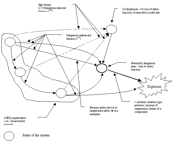
Figure 1 : Safety device failure effects
4. Safety level assessement procedure
The system's safety integrity level is assessed in accordance with the following procedure that breaks down the assessment into the five following stages with logical links :
· 1st stage : functional analysis,
· 2nd stage : failure rate prediction
· 3rd stage : failure modes, effects and criticality analysis,
· 4th stage : modelling of the system's various states,
· 5th stage : system safety integrity level assessment.
This procedure is defined in reference [11], which is confidential.
4.1 Assumptions
This assessment does not take into account :
· common mode failures,
· systematic errors,
· connection failures,
· errors linked to cabling,
· human errors.
4.2 First stage : functional analysis
The purpose of the functional analysis is to identify the functions to be fulfilled by the system. It is also intended to explain the system's operation by establishing a link between the hardware and software functions. This stage is the assessment's input point. It is sufficiently accurate to identify failures with an impact on the system's safety.
Several functional analysis procedures may be used to explain the operation of automatic systems :
- functional block diagram procedure,
- SADT procedure,
- SA_RT procedure,
- etc.
4.3 Second stage : failure rate prediction
4.3.1 Purpose
The purpose of the failure rate prediction is not to assess the system's reliability. Calculations are only conducted for the components with a risk in relation to safety, in order to quantify the dangerous failure rate. To that end, a calculation makes it possible to assess an equivalent failure rate of the system. This calculation comprises : component failure rates, component stress, climatic environment, component quality, etc.
The failure rate prediction allows us to quantify the FMECA (Failure Modes Effects and Criticality Analysis - See 3rd stage) and to identify the contribution of the various failure modes to the system's unsafe situation.
4.3.2 Calculation assumptions
Failure rate calculations are grounded on databases that supply a basic failure rate for each type of component. This basic failure rate is modulated according to corrective factors according to the environment and component.
The databases (for information) are :
- MIL HDBK 217 (Military Handbook);
- CNET,
- etc.
The database used by INERIS for the failure rate calculations is the CNET RDF 93 rev. 2/95 database (see reference [12]). Calculations are conducted with the RAM Commander version 6.1 software. The selected calculation assumptions are as follows :
· temperature or pressure measurement device environment : GM; + 40 °C (fixed on a track, motor, …),
· power supply shut off device environment : GF; + 40 °C,
· temperature or pressure measurement device component quality : “ non-CECC ” or equivalent; stress rate inferior or equal to 50%; CMS machine assembly,
· power supply shut off device component quality : “ CECC ” or equivalent; stress rate inferior or equal to 50%; assembly on card “ components to be punched ” manual assembly.
4.3.3 Experience of returns
There is experience of returns to the company manufacturing the low level detection system. These systems are mainly installed to detect petroleum product levels in tankers.
By comparing the number of devices returned to the manufacturer with the pool of installed devices and by assuming :
· a balanced distribution between detected failures and undetected failures,
· a reliability according to the constant failure rate exponential law.
We obtain a failure rate grounded on the returns experience “ sixfold ” lower than the predicted failure rate. This can be explained by :
· certain devices are probably being stored for availability reasons,
· failing devices are probably not systematically returned in the event of fault (guarantee period expired, …).
In the following safety integrity level calculations, the selected value is that of the predicted reliability.
In addition, this “ sixfold ” ratio between the predicted values and measured values is less than the order of magnitude range of failure rates within a safety integrity level as defined by the IEC 61508 standard.
4.4 Third stage : failure modes effects and criticality analysis (FMECA)
After identifying the components fulfilling the functions (hardware and software), identified by the functional analysis, the failure modes and their effects on the system's operation must be analysed in the scope of this study. Certain standards formalise this type of study (MIL STD 1629, …), others give values to distribute the components' failure modes (CNET, manufacturer data, …).
The purpose of this stage is to analyse the failures to identify “ dangerous ” failure modes, and to quantify the probability of failure occurrence.
The Failure Modes Effects and Criticality Analysis (FMECA) is conducted at electronic component detail level for the safety device. The purpose of this analysis is :
· to identify the “ dangerous ” failure modes to assess the “ dangerous ” failure rates leading to the hazardous event, while assessing a coverage rate for the various tests;
· to identify the possible preventive maintenance provisions to be integrated to guarantee a safety integrity level in compliance with the defined goals.
Failures are classified in 4 classes :
· dangerous detected failures whose effects are on safety and availability ( ),
),
· dangerous un-detected failures whose effects are only on safety ( ),
),
· non-dangerous detected failures whose effects are only on availability ( ),
),
· non-dangerous and undetected failures whose effects are only on availability ( ).
).
( =  Dangerous, Undetected ;
  = Safe).
= Safe failure : i.e. a failure that results in system fallback (safe situation for safety),
= Unsafe failure : failure whose consequence leads to a dangerous state from the standpoint of safety.
The following diagram give further details of this notion of distribution of failures according to their effect.
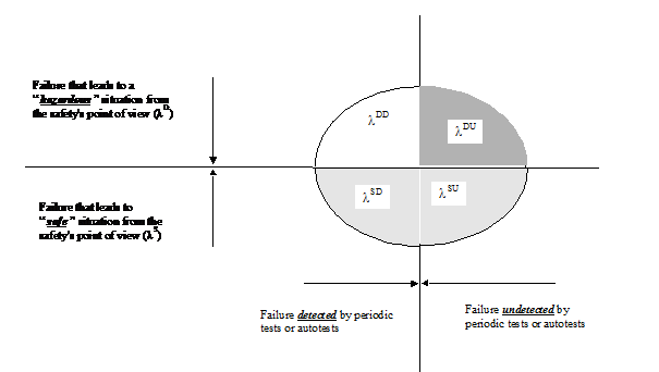
Figure 2 : Failure distribution according to their effect
References [12] and [13] state the failure mode distribution for various components.
4.5 Fourth stage : modelling of the system's various states
There are three system types according to the various encountered systems :
[1] Failsafe systems
[2] Non-redundant systems
[3] Redundant systems
The system's dangerous failure probability calculation is different according to the various types of system.
4.5.1 Failsafe systems
Failsafe systems are systems in which the failure modes of all components of the system lead to a “ safe state ” in relation to safety. For these systems, there is no use in calculating the dangerous failure probability as the lDU dangerous failure rate does not exist
4.5.2 Non-redundant systems
Non-redundant systems are “ simple ” systems in which the safety function can be lost in the event of failure. Two states are possible : safe state or dangerous state. The calculation of the dangerous failure probability for the systems comes down to a specific reliability calculation depending on the dangerous failure rate (lDU - identified in FMECA) and with the same duration as the preventive maintenance operations.
4.5.3 Redundant systems
In the event of redundant systems, the safety function can be lost due to combinations of failures depending on the logic implemented within the safety system. There are several safety integrity level quantitative assessment procedures for such systems. The main drawback of the more traditional procedures such as the analysis by fault tree system, or the analysis by reliability block diagram, is that they do not always take into account the time aspect, test periodicity, coverage levels, as well as the repair rate.
The various failure and operating states can be modelled with MARKOV graphs, by integrating the time aspect of the preventive maintenance tests, the autotests as well as the coverage rate, as the electronic systems are subject to a failure law of exponential form with a constant failure rate.
4.5.3.1 Influence of testability on safety
For safety purposes, the state of the resources must be known on a permanent basis to see if hidden (or dormant or latent) failures liable to mask the safety function exist. These dormant failures are only detected during periodic tests voluntarily conducted by the user.
A test policy is useless for failsafe systems as each failure leads to a “ safe ” position in relation to safety.
On the contrary, for systems that are neither failsafe nor autotestable and on which dangerous failures exist, a test policy to detect the “ dangerous failures ” (with a risk for safety) is required.
These tests must be conducted according to a periodicity grounded on the characteristics of the various elements constituting the system. Dangerous failures can be detected in two ways :
· Either by the test and autotests system of the safety system for detectable failures (lDD),
· Or during verification operations for non-detectable failures (lDU).
The PLC's reliability level is not increased by testability. It just makes it possible to ensure that resources are still available : to read the inputs and control the outputs, on the one hand, and to make sure that the processing modules are still functional, on the other hand. Only dangerous failure detection comes into play. It is possible to detect and switch to safe position in the event of failure, thanks to this test, and therefore to better guarantee safety. The following diagram shows the impact of testability on safety, and the impact of a state changeover test policy conducted every 24 hours or every 6 months on safety.
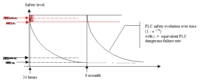
Figure 3 : Testability impact on safety
On this figure is shown that PFD is the probability of failure and PFDAVG is the average probability of failure which is aproximately the half of PFD (see PFD (1)) for safety systems with short period state changeover test, and the third of PFD (see PFD (2)) for safety systems with long period state changeover test. This difference is due, for electronic systems, to a constant failure rate (l) and to the reliability calculation with the exponential law.
4.5.3.2 Graph establishment
References [10] and [14] stipulate the procedure and various stages of system modelling. State graphs are represented below for each safety function. Modelling is achieved with “ states ” that the system is liable to enter. There are 3 states in most cases :
State 2 represented as follows : 
This state corresponds to the modelling of redundancy. In this state, all implemented resources are present and operate in a nominal manner.
State 1 represented as follows :
This state corresponds to the modelling of redundancy downgraded by the dangerous failure of a hardware element on one of two channels. In this state, all implemented resources are not present. It is an undetected dangerous failure state. Safety is still guaranteed.
State 0 represented as follows : 
This state corresponds to the modelling of the loss of redundancy due to the dangerous failure of several hardware elements from the channels. In this state, safety is no longer guaranteed and in the event that the safety function is called upon, the system will not go to safe position.
The “ P ” probability of being in “ 0 ” state is designated by PFD(t) in the IEC 61508 standard. The meanning of PFD(t) value is the value defined in the previous paragraph.
4.5.3.3 Assumptions
MARKOV graph modelling for the studied systems by INERIS was grounded on the following assumptions :
[1] failure rates (l) and repair rates (m) are assumed constant to make it possible to model and calculate the safety level with MARKOV graphs.
[2] The mission time (TI) corresponds to the intervals between the OFF LINE periodic test times. All test rates concerning the aptitude to detect state changeovers (mPTi) are stated for each arc of each graph.
[3] Inputs and outputs do not go to the safe state if the power supply is cut off.
[4] The common failure modes, and the systematic errors are assumed equal to those defined in reference [14]. lD common mode failures or faults have the specificity of affecting all lines at the same time. The selected values are those defined in the same document.
4.5.4 System modelling example
Two active redundancy systems are modelled as follows
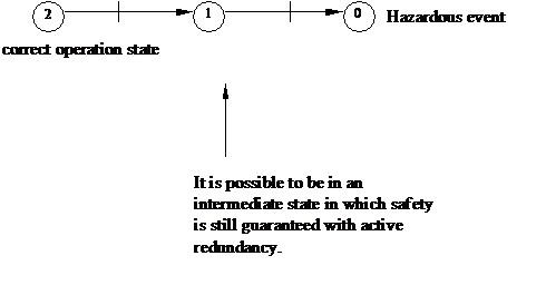
Figure 4 : Redundant system state modelling
This graph is equivalent to the following graph :

Figure 5 : Redundant system state reduced modelling
The “ P ” probability of being in a “ 0 ” state therefore depends on a failure rate that in turn depends on time T : P = L(t) x T.
This example shows that the more time T increases and the more the probability of being at “ 0 ” state increases.
4.6 Fifth stage : Safety integrity level assessment
The system's various states were modelled with the fourth stage. This stage consists of resolving the mathematical calculation and comparing the level achieved by the system with the classifications of the IEC 61508 standard.
The dangerous failure probability calculation (PFD) is a function of a system failure rate (function variable over time) and of a duration, in most cases. Therefore, the safety integrity level calculation is a specific reliability calculation in which safety is equal : either to the reliability during a time equal to that of the auto-test's overall time, or to that of the preventive maintenance intervals.
5. Application of safety integrity level assessement procedure
5.1 Case study of diode safety barrier
5.1.1 Description and functional analysis
Diode safety barriers are assemblies incorporating shunt diodes or diode chains (including zener diodes) protected by fuses or resistors or a combination of these.
The diodes, zener diodes in the example of figure 6, limit the voltage applied to an intrinsically safe circuit and a following infallible current limiting resistor limits the current which can flow into the circuit. These assemblies are intended for use as interfaces between intrinsically safe circuits and non-intrinsically safe circuits.
The diode safety barrier is manufactured as an individual apparatus rather than a part of a larger apparatus and, as it contains both intrinsically safe circuits and non-intrinsically safe circuits, the barrier is an associated apparatus and shall be :
· either protected by an alternative type of protection listed in EN 50014 [1] for use in the appropriate explosive gas atmosphere,
· or situated outside the explosible atmosphere.
Besides, the barrier shall comply with requirements of EN 50020 [7] which specify in particular for safety devices that the assembly must contain :
· three diodes or three diode chains for category “ ia ” (safe with two faults),
· two diodes or two diode chains for category “ ib ” (safe with one fault).
The choice of category “ ia ” for an intrinsically safe apparatus allows the use of such an electrical apparatus in hazardous areas where explosive gas atmosphere is present continuously or for long periods.
The choice of category “ ib ” for an intrinsically safe apparatus allows the use of such an electrical apparatus in hazardous areas where explosive gas atmosphere is likely to occur in normal operation.

Figure 6 : zener barrier
5.1.2 Failure rate prediction
Results of the calculation for a low power (1.5 W) Zener diode give a failure rate of l = 2.4*10-9/hr grounded on assumptions defined in paragraph 4.3.
5.1.3 FMECA
5.1.3.1 ATEX classification
According to ATEX requirements this failure mode is impossible because :
· According to EN 50020, during normal operation, a component can’t fail if it works under the 2/3 of its maximum characteristics. This component is considered as an unfaillible component.
· According to EN 50020 if a zener diode fails to short-circuit during the transient period, the fuse can blow if the maximum current is over 1.7 of the nominal current of the fuse. In this case the maximum power dissipated by the diode is lower than its maximum power characteristics, and the safety function of the safety barrier is guarranted. If the maximum current is lower than 1.7 nominal current, then the power dissipated in the diode is lower than its maximum power characteristics.
· During worst functionning (maximum input voltage up to 250 Volts applied to the barrier inputs), the fuse will blow in a very short time (usually lower than 1 milli-second) and the consequence of this worst functionning is a “ safe state ”, so the safety barrier has to be changed, and there is no hazard. In addition, during the short time of the blowing of the fuse, the functionning power rate of the components (Zener diodes and resistors) complies with the 2/3 rules of their maximum characteristics. So the Zener diode have a low probability to get a short circuit because of the worst functionning of the associated electrical circuit connected to the barrier inputs.
5.1.3.2 IEC 61508 / CNET classification
According to reliability of the CNET standard (see reference [12]) and of other reliabiity standards, a component has several failures modes which not take into account the working conditions of the component. Only the failure rate take into account the working conditions of the component.
The CNET's database gives the following failure mode for a low power Zener diode (1.5 W) :
· 10% for voltage drifts
· 20% for open circuit and
· 70% for short-circuit.
5.1.3.2.1 Safe state
The loss of the safety function leading to a safe position regarding safety is achieved if one of the three diodes is short-circuited.
5.1.3.2.2 Dangerous state
The hazardous event in relation to the explosion would be the loss of intrinsic safety characteristics i.e. the following failure mode : “ open circuit on the 3 diodes ”.
Safety level assessment
5.1.3.3 Dangerous state
Modelling by MARKOV graph is not required for this type of system, and the safety level calculation (3 diodes in open circuit) comes down to a specific reliability calculation in which the probability of event occurrence is equal to Q(t) = 1 - R(t) with :
· 
· then  =
=  for the loss of 3 diodes in open circuit (C.O.)
· hence  and
and
· 
With a failure distribution assumption of 20% for the open system failure mode and 70% for the short-circuit failure mode, and a failure rate for a low power Zener diode (1.5 W) of = 2.4*10-9/hr, we obtain a of 4.8*10-10/hr for one diode, a EQ for the 3 diodes of 2.6*10-10/hr.
The results of the calculations for the dangerous state (loss of intrinsic safety characteristics) are :
· Probability for the dangerous state for one year duration without tests :
= 2.28*10-6.
· Probability for the dangerous state for ten years duration without tests :
= 2.28*10-5
5.2 These are the “ worst cases ” assumptions for the SIL calculations
5.2.1.1 Safe state
The consequence of the failure of one of the three diodes in “ short circuit ” is a safe state because the fuse will blow in a very short time (usualy lower than 1 milli-second) and during this blowing the functionning rate of the component (zener diodes and resistors) complies with the 2/3 rules of their maximum characteristics.
With the same failure distribution assumptions and failure rate, the probability of this event is  with :
· 
· and 
· Probability of safety function loss leading to a safe state for one year duration :
 = 4.4*10-5
· Probability of safety function loss leading to a safe state for ten years duration :
= 4.4*10-4
5.2.2 IEC 61508 quality requirement observance examination
For the safe states, there is no need to check the Zener barrier because this unit will be replace by a new one to keep the well functionning of the safety-function.
The Zener diode safety barrier is a device for which 20% of failures lead to the hazardous event. This architecture can tolerate two failures and has a failsafe fraction of 80%.
This Zener diode safety barrier reachs the SIL 4 level qualitative and quantitative requirements for a one year period (and for a period of 10 years) without periodic test for a safety related protection system.
In theory, the Zener diode safety barrier reachs the SIL 4 qualitative and quantitative requirements for a period of 43 years. After this period, the Zener diode safety barrier reachs the SIL 3 quantitative requirements. This result must not be taken into account because the calculations basis are not valid after a period of ten years for electronic components (after this period, the failure rate is not constant).
5.3 Case study of Safety level detection safety device
A system already “ ia ” intrinsic safety certified formed the subject of an assessment by INERIS in accordance with requirements of standard IEC 61508.
5.3.1 Functional analysis
We represent the case of a safety low level detection system installed in a tank containing liquid or liquefied hydrocarbons. The system is constituted of one detector connected to a processing unit to detect a low level in order to shut off the electric power.
5.3.2 Failure rate prediction
Grounded on assumptions mentioned in paragraph 4.3, the calculation results give a failure rate of = 4*10-6/h for the detector, and of = 1.1*10-6/h for the processing unit.
5.3.3 FMECA
The hazardous event in relation to safety for the safety level detection system is the loss of low level detection. The system's dangerous failure rate was calculated grounded on the detailed FMECAs. Results are as follows :
· A dangerous failure rate of 2*10-6/h for the detector i.e. an FSF of 49%
· A dangerous failure rate of 1.5*10-7/h for the processing unit, i.e. an FSF of 85%
· i.e. for the full system, an FSF under 60%
5.3.4 Safety level assessment
MARKOV graph modelling is not required, and the safety level calculation comes down to a specific reliability calculation in which the probability of occurrence of this event is  .
.
By assuming a dangerous failure rate for the detector of 2*10-6/h and 1.5*10-7/h for the processing unit, we obtain the following values for a year :
Safety function loss of low level detection of 1.7*10-2
5.3.5 IEC 61508 requirement observance examination
If a processing unit design in simple chain tolerance to “ 0 ” failures is selected and if the following values are selected for the overall safety level detection system : a failsafe fraction (FSF) inferior to 60% and a PFD of 1.7*10-2, the safety level detection system can be graded as safety related control system, and is compliant with the SIL 1 level qualitative and quantitative requirements for a one year term and for operation on demand.
5.4 Case study of pressure and température safety devices
5.4.1 Functional analysis
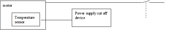
Figure 7 : Motor protection device
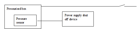
Figure 8 : Pressurised box protection device
5.4.2 Failure rate prediction
With the assumptions defined in paragraph 4.3, the results of the calculations give the following failure rate :
· Temperature sensor = 5*10-9/h and
· Power supply shut off device = 1.1*10-6/h
5.4.3 FMECA
Both architectures are similar. The safety function loss leads to an explosion risk under explosive atmosphere in both cases. The safety function loss occurs in the event of pressure sensor or power supply shut off device dangerous failure for the first architecture. The safety function loss occurs in the event of temperature sensor or power supply shut off device dangerous failure for the second architecture.
The detailed FMECAs at component level were conducted on a low level detection system in the event of LPG storage (see the values of chapter 5.3) in simple chain. Assuming a similar architecture for the power supply shut off device, the dangerous failure rate is 1.5*10-7/hr i.e. an FSF of 85%.
5.4.4 Safety level assessment
If a power supply shut off device design in simple chain based on discrete electronics is selected, the MARKOV graph modelling is not required, and the safety level calculation comes down to a specific reliability calculation in which the probability of occurrence of this event is equal to with
By assuming a failure rate of 5*10-9/hr for the temperature sensor, a dangerous failure distribution of 100%, and a dangerous failure rate for the power supply shut off device of 1,5*10-7/hr, we obtain the following values for a year :
Safety function loss leading to an explosion risk= 1.35*10-3
5.4.5 IEC 61508 requirement observance examination
If the power supply shut off device design in simple chain tolerance to “ 0 ” failure, a failsafe fraction of 85% and a PFD of 1.35*10-3 are selected, the device must meet the SIL 2 level quality and quantity requirements for operation on demand for a year and for a safety related protection system.
6. Conclusions
6.1 Main differences between ATEX standards and IEC 61508
There are differences between hardware fault tolerance of IEC 61508 and of ATEX standards. The requirements of hardware fault tolerance of IEC 61508 are defined to their consequence regarding the loss of the safety function. Those requirements are a measurement of the effectiveness of a safety-related device.
The requirements of hardware fault tolerance of ATEX standards are defined to their consequence regarding the explosion hazard.
According to some ATEX standards, if some construction principles are met, then the component is considered as infaillible. In IEC 61508 and reliability standards and databases the concept of infaillible component is not considered.
6.2 Classification of ATEX safety devices according to IEC 61508
IEC 61508 standard requirements (see reference [10]) are :
· System development cycle requirements around a safety life cycle and in terms of related documentation (Part 1).
· Qualitative and quantitative technical requirements in presence of faults (Parts 1 and 2).
· Technical requirements in relation to software design and validation (Part 3).
INERIS only checked the qualitative and quantitative technical requirements in the presence of faults which were taken into account. The system's overall safety validation by functional safety tests, behaviour tests on defect and tests related to sizing and compliance with the environmental parameters were not conducted by INERIS. Similarly, INERIS did not check whether the requirements of the system's development cycle around a safety life cycle was taken into account and did not check the related documentation.
There are two types of failures according to the consequences for safety, in accordance with the qualitative and quantitative technical requirements in the presence of faults, set out in the IEC 61508 standard. These failures are :
· Safe failures, i.e; failures whose consequences lead to system fallback (safe situation in relation to safety),
· Dangerous failures, i.e. failures resulting in a dangerous state in relation to safety.
In accordance with the ATEX standards, failures are graded according to their effect in relation to the ignition of explosive atmospheres. These types of failures or faults correspond to the loss of safety function as defined in the IEC 61508 standard.
Ours conclusions concerning the safety devices’ grading used in applications liable to form an explosive atmosphere are as follows :
· Safety devices must meet the requirements of applicable standards (see reference documents [1] to [9]).
· The only purpose of grading safety devices in accordance with the IEC 61508 standard requirement is to assess their capacity to guarantee the safety function for which they were designed during the time.
· Devices can be graded in accordance with the ATEX standard requirements and to those of the IEC 61508 standard if the effect of dangerous failures and safe failures as defined in the IEC 61508 standard correspond to the failures as defined in the ATEX standard, and that the failures can lead to the ignition of explosive atmospheres.
There are two main types of configurations :
· Configurations in which the undetected dangerous failure of a safety device does not directly lead to an explosion (e.g. case of a temperature measurement device and of an electric motor power supply shut off device in the event of overheating). In this case, the probability of explosion occurrence is subject to : motor overheating AND failure of the safety devices AND presence of an explosive atmosphere. This type of situation could correspond to what the IEC 61508 standard refers to as the “ safety related protection systems ”. These are the devices under the scope of the SAFEC project.
· Configurations in which an undetected dangerous failure of the safety device does not lead to an explosion but to another hazard (case of the level detection system). This case could correspond to what the IEC 61508 standard refers to as the “ safety related control systems ”. These devices are not under the scope of the SAFEC project because their use is under the knowledge and under the responsability of the end user. (A level detection system would fall into the first category if it was used as part of a submersible pump, such that ignition could occur if the level dropped below the level of the pump).
These conclusions only encompass safety devices used in applications under explosive atmospheres studied in paragraph 4 of this document, and with an autonomous safety function.
These conclusions are only valid if preventive maintenance is conducted. The purpose of these preventive maintenance operations is to detect, when it’s possible, component failures leading to a dangerous state.
7. Références
[1] EN 50014 Electrical apparatus for potentially explosive atmospheres. General requirements[1].
[2] EN 50015 Electrical apparatus for potentially explosive atmospheres. Specific requirements for the protective mode "o" oil immersion[2].
[3] EN 50016 Electrical apparatus for potentially explosive atmospheres. Specific requirements for the protective mode : pressurised apparatus "p"[3].
[4] EN 50017 Electrical apparatus for potentially explosive atmospheres. Specific requirements for the protective mode : powder filling "q"[4].
[5] EN 50018 Electrical apparatus for potentially explosive atmospheres. Specific requirements for the protective mode : flameproof enclosure "d"[5].
[6] EN 50019 Electrical apparatus for potentially explosive atmospheres. Specific requirements for the protective mode : increased safety "e"[6].
[7] EN 50020 Electrical apparatus for potentially explosive atmospheres. Specific requirements for the protective mode : intrinsic safety "i"[7].
[8] EN 50028 Electrical apparatus for potentially explosive atmospheres. Specific requirements for the protective mode : encapsulation "m"[8].
[9] Reports on task 1 and 2 of the SAFEC project
[10] CEI 61508 - version FDIS of 1998-07-31
Functional Safety : safety-related systems (part 1 to 7)
[11] LSSE - 95.14 dated April 1995 (document confidential to INERIS)
(Analysis and assessment procedure for the safety and availability levels of safety automations by Markovian modelling)
[12] RDF 93
Recueil de données de fiabilité des composants électroniques (Electronic component reliability data log)
[13] A.BIROLINI
Quality and reliability of technical Systems (Ed. Springer - Verlag)
[14] “ Draft 5 (5/13/1996 - ISA technical report ”)..
English
