- Home
- Machinery Directive
- History of the Machinery Directive 2006/42/EC
- Machinery directive 2006/42/EC
- Whereas of machinery directive 2006/42/EC
- Articles of machinery directive 2006/42/EC
- Article 1 of machinery directive 2006/42/EC - Scope
- Article 2 of machinery directive 2006/42/EC - Definitions
- Article 3 : Specific Directives of machinery directive 2006/42/EC
- Article 4 : Market surveillance of machinery directive 2006/42/EC
- Article 5 : Placing on the market and putting into service - machinery directive 2006/42/EC
- Article 6 : Freedom of movement - machinery directive 2006/42/EC
- Article 7 : Presumption of conformity and harmonised standards - machinery directive 2006/42/EC
- Article 8 : Specific measures - machinery directive 2006/42/EC
- Article 9 : Specific measures to deal with potentially hazardous machinery - machinery directive 2006/42/EC
- Article 10 : Procedure for disputing a harmonised standard - machinery directive 2006/42/EC
- Article 11 : Safeguard clause - machinery directive 2006/42/EC
- Article 12 : Procedures for assessing the conformity of machinery - machinery directive 2006/42/EC
- Article 13 : Procedure for partly completed machinery - 2006/42/EC
- Article 14 : Notified bodies - machinery directive 2006/42/EC
- Article 15 : Installation and use of machinery - machinery directive 2006/42/EC
- Article 16 : CE marking - machinery directive 2006/42/EC
- Article 17 : Non-conformity of marking - machinery directive 2006/42/EC
- Article 18 : Confidentiality - machinery directive 2006/42/EC
- Article 19 : Cooperation between Member States - machinery directive 2006/42/EC
- Article 20 : Legal remedies - machinery directive 2006/42/EC
- Article 21 : Dissemination of information - machinery directive 2006/42/EC
- Article 22 : Committee - machinery directive 2006/42/EC
- Article 23 : Penalties - machinery directive 2006/42/EC
- Article 24 : Amendment of Directive 95/16/EC - machinery directive 2006/42/EC
- Article 25 : Repeal - machinery directive 2006/42/EC
- Article 26 : Transposition - machinery directive 2006/42/EC
- Article 27 : Derogation - machinery directive 2006/42/EC
- Article 28 : Entry into force - machinery directive 2006/42/EC
- Article 29 : Addressees - machinery directive 2006/42/EC
- ANNEX I of machinery directive 2006/42/EC - Summary
- GENERAL PRINCIPLES of annex 1 of machinery directive 2006/42/EC
- 1 ESSENTIAL HEALTH AND SAFETY REQUIREMENTS of annex 1 - definitions - machinery directive 2006/42/EC
- Article 1.1.2. Principles of safety integration of annex 1 machinery directive 2006/42/EC
- Article 1.1.3. Materials and products annex 1 machinery directive 2006/42/EC
- Article 1.1.4. Lighting - annex 1 machinery directive 2006/42/EC
- Article 1.1.5. Design of machinery to facilitate its handling - annex 1 machinery directive 2006/42/EC
- Article 1.1.6. Ergonomics - annex 1 machinery directive 2006/42/EC
- Article 1.1.7. Operating positions - annex 1 machinery directive 2006/42/EC
- Article 1.1.8. Seating - annex 1 machinery directive 2006/42/EC
- Article 1.2.1. Safety and reliability of control systems - annex 1 of machinery directive 2006/42/EC
- Article 1.2.2. Control devices - annex 1 of machinery directive 2006/42/EC
- Article 1.2.3. Starting - annex 1 of machinery directive 2006/42/EC
- Article 1.2.4. Stopping - annex 1 of machinery directive 2006/42/EC
- Article 1.2.4.4. Assembly of machinery - Annex 1 of machinery directive 2006/42/EC
- Article 1.2.5. Selection of control or operating modes - annex 1 of machinery directive 2006/42/EC
- Article 1.2.6. Failure of the power supply - annex 1 of machinery directive 2006/42/EC
- Article 1.3. PROTECTION AGAINST MECHANICAL HAZARDS - annex 1 of machinery directive 2006/42/EC
- Article 1.4. REQUIRED CHARACTERISTICS OF GUARDS AND PROTECTIVE DEVICES - annex 1 of machinery directive 2006/42/EC
- Article 1.5. RISKS DUE TO OTHER HAZARDS - annex 1 of machinery directive 2006/42/EC
- Article 1.6. MAINTENANCE - annex 1 of machinery directive 2006/42/EC
- Article 1.7. INFORMATION - annex 1 of machinery directive 2006/42/EC
- Article 2. SUPPLEMENTARY ESSENTIAL HEALTH AND SAFETY REQUIREMENTS - annex 1 machinery directive 2006/42/EC
- Article 3. SUPPLEMENTARY ESSENTIAL HEALTH TO THE MOBILITY OF MACHINERY - annex 1 machinery directive 2006/42/EC
- Article 4. SUPPLEMENTARY REQUIREMENTS TO OFFSET HAZARDS DUE TO LIFTING OPERATIONS of machinery directive 2006/42/EC
- Article 5. SUPPLEMENTARY ESSENTIAL HEALTH AND SAFETY REQUIREMENTS FOR UNDERGROUND WORK of machinery directive 2006/42/EC
- Article 6. SUPPLEMENTARY REQUIREMENTS - HAZARDS DUE TO THE LIFTING OF PERSONS of machinery directive 2006/42/EC
- Annex II : Declarations of CONFORMITY OF THE MACHINERY, DECLARATION OF INCORPORATION - machinery directive 2006/42/EC
- Annex III of machinery directive 2006/42/EC - CE marking
- Annex IV of machinery directive 2006/42/EC
- Annex V of machinery directive 2006/42/EC
- Annex VI of machinery directive 2006/42/EC
- Annex VII - Technical file for machinery - machinery directive 2006/42/EC
- Annex VIII - Assessment of conformity of machinery directive 2006/42/EC
- Annex IX of machinery directive 2006/42/EC - EC type-examination
- Annex X of machinery directive 2006/42/EC - Full quality assurance
- Annex XI of machinery directive 2006/42/EC - Minimum criteria for the notification of bodies
- Annex XII of machinery directive 2006/42/EC - Correlation table between machinery directive 2006/42/CE and MD 1998/37/CE
- Machinery directive 1998/37/EC
- considerings of machinery directive 1998/37/CE
- articles of 1998/37/EC machinery directive
- Annex I of 1998/37/CE machinery directive
- Annex II of 1998/37/EC machinery directive
- Annex III of machinery directive 1998/37/CE
- Annex IV of machine directive 1998/37/EC
- Annex V of machines directive 1998/37/CE
- Annex VI of machines directive 1998/37/EC
- Annex VII of machines directive 1998/37/EC
- Annex VIII of 1998/37/CE machine directive
- Annex IX of machinery directive 1998/37/CE
- Machinery directive 1989/392/EC
- whereas of machinery directive machines 1989/392/EEC
- articles of machinery directive 1989/392/EEC
- Annex I of machinery directive 1989/392/EEC
- Annex II of machine directive 1989/392/EEC
- Annex III of machinery directive 1989/392/EEC
- Annex IV of machinery directive 1989/392/EEC
- Annex V of machinery directive 1989/392/EEC
- Annex VI of machine directive 1989/392/EEC
- Annexe VII of machinery directive 1989/392/EEC
- Amendments of 1989/392/EEC directive
- ATEX directives
- ATEX 94/9/EC directive
- Whereas of ATEX 94/9/CE directive
- Articles of ATEX 94/9/CE directive
- article 1 ATEX 94/9/EC directive
- article 2 ATEX 94/9/EC directive
- article 3 ATEX 94/9/EC directive
- article 4 : ATEX 94/9/EC directive
- article 5 : ATEX 94/9/EC directive
- article 6 : ATEX 94/9/EC directive
- article 7 : ATEX 94/9/EC directive
- article 8 ATEX 94/9/EC directive
- article 9 : ATEX 94/9/EC directive
- article 10 : ATEX 94/9/EC directive
- article 11 : ATEX 94/9/EC directive
- article 12 : ATEX 94/9/EC directive
- article 13 : ATEX 94/9/EC directive
- article 14 : ATEX 94/9/EC directive
- article 15 : ATEX 94/9/EC directive
- article 16 : ATEX 94/9/EC directive
- ANNEX I of ATEX 94/9/EC directive : CRITERIA DETERMINING THE CLASSIFICATION OF EQUIPMENT-GROUPS INTO CATEGORIES
- ANNEX II of ATEX 94/9/EC : directive ESSENTIAL HEALTH AND SAFETY REQUIREMENTS -EHSR
- ANNEX III of ATEX 94/9/EC directive : MODULE EC-TYPE EXAMINATION
- ANNEX IV of ATEX 94/9/EC directive : MODULE PRODUCTION QUALITY ASSURANCE
- ANNEX V of ATEX 94/9/EC directive : MODULE PRODUCT VERIFICATION
- ANNEX VI of ATEX 94/9/EC directive : MODULE CONFORMITY TO TYPE
- ANNEX VII of ATEX 94/9/EC directive : MODULE PRODUCT QUALITY ASSURANCE
- ANNEX VIII of ATEX 94/9/EC directive : MODULE INTERNAL CONTROL OF PRODUCTION
- ANNEX IX of ATEX 94/9/EC directive : MODULE UNIT VERIFICATION
- ANNEX X of ATEX 94/9/EC directive : CE Marking - Content of the EC declaration of conformity
- ANNEX XI of ATEX 94/9/EC directive: NOTIFICATION OF BODIES
- ATEX 99/92/EC Directive
- ATEX DIRECTIVE 2014/34/UE
- whereas of 2014/34/UE ATEX directive
- Articles of ATEX 2014/34/UE directive
- Annex 1 of ATEX 2014/34/UE directive
- Annex 2 of the ATEX 2014/34/UE directive
- Annex 3 of ATEX 2014/34/UE directive
- Annex 4 of ATEX 2014/34/UE directive
- Annex 5 of ATEX 2014/34/UE directive
- Annex 6 of ATEX 2014/34/UE directive
- Annex 7 of ATEX 94/9/EC directive
- Annex 8 of the ATEX 2014/34/UE directive
- Annex 9 of the ATEX 2014/34/UE directive
- Annex 10 of ATEX 2014/34/UE directive
- Annex 11 of ATEX 2014/34/UE directive
- Annex 12 of the ATEX 2014/34/UE directive
- Audits in Ex field - EN 13980, OD 005 and EN ISO/CEI 80079-34
- New ATEX directive
- RASE european project
- ATEX 94/9/EC directive
- IECEX
- Standardization & European Regulation
- Safety of machines : Standardization and European regulations
- European regulation for machines - standardization for machines - harmonized standards
- Standardization in machinery
- EN ISO 12100 - Décembre 2010
- EN ISO 12100-1 - January 2004
- EN ISO 12100-1:2003/A1
- EN ISO 12100-2 November 2003
- EN ISO 12100-2:2003/A1
- EN ISO 14121-1 September 2007
- ISO/TR 14121-2 - 2007
- EN 50205:2002 standard - Relays with forcibly guided (mechanically linked) contacts
- ISO 11161:2007
- ISO 13849-1:2006
- ISO 13849-2:2012
- ISO 13850:2006 - Safety of machinery -- Emergency stop -- Principles for design
- ISO 13851:2002 - Safety of machinery -- Two-hand control devices -- Functional aspects and design principles
- ISO 13854:1996 Safety of machinery - Minimum gaps to avoid crushing of parts of the human body
- ISO 13855:2010 - Safety of machinery -- Positioning of safeguards with respect to the approach speeds of parts of the human body
- ISO 13856-1:2013 Safety of machinery -- Pressure-sensitive protective devices -- Part 1: General principles
- ISO 13856-2:2013 - Safety of machinery -- Pressure-sensitive protective devices -- Part 2: General principles for design testing
- ISO 13856-3:2013 Safety of machinery -- Pressure-sensitive protective devices - Part 3: General principles for design
- ISO 13857:2008 Safety of machinery -- Safety distances to prevent hazard zones
- ISO 14118:2000 - Safety of machinery -- Prevention of unexpected start-up
- ISO 14119:2013- Interlocking devices associated with guards
- ISO 14120:2002 - Guards -- General requirements for the design and construction
- ISO 14122-1:2001 - Permanent means of access to machinery
- ISO 14122-2:2001 - Permanent means of access to machinery
- ISO 14122-4:2004 - Permanent means of access to machinery
- ISO 14123-1:1998 - Reduction of risks to health from hazardous substances emitted by machinery
- ISO 14123-2:1998 - Reduction of risks to health from hazardous substances emitted by machinery
- ISO 14159:2002 - Hygiene requirements for the design of machinery
- ISO 19353:2005 -- Fire prevention and protection
- ISO/AWI 17305 - Safety of machinery - Safety functions of control systems
- ISO/DTR 22100-2 - Safety of machinery -- Part 2: How ISO 12100 relates to ISO 13849-1
- ISO/TR 14121-2:2012 - Risk assessment - Part 2: Practical guidance
- ISO/TR 18569:2004 - Guidelines for the understanding and use of safety of machinery standards
- ISO/TR 23849:2010 - Guidance on the application of ISO 13849-1 and IEC 62061 in the design of safety-related control systems
- STABILITY DATES FOR Machinery STANDARDS
- harmonized standards list - machinery-directive 2006/42/CE
- Publication of harmonised standards for machinery directive 2006/42/EC - 9.3.2018
- Harmonized standard list - machinery directive 2006/42/EC - 9.6.2017
- Harmonized standards for machinery - OJ C 2016/C173/01 of 15/05/2016
- Harmonized standards for machinery -OJ C 2016/C14/102 of 15/01/2016
- Harmonized standards for machinery - corrigendum OJ C 2015/C 087/03 of 13/03/2015
- harmonized standards for machinery - OJ C 2015/C 054/01 of 13/02/2015
- Application guide for machinery directive 2006/42/EC
- Guide to application of the machinery directive 2006/42/CE - July 2017
- Guide to application of the Machinery Directive 2006/42/EC - second edition June 2010
- Guide to application of machinery directive - 1-2 : The citations
- Guide to application of machinery directive - § 3 to § 31 The Recitals
- Guide to application of machinery directive - § 32 to § 156 - The Articles
- Guide to application of machinery directive - § 157 to § 381 - Annex I
- Guide to application of machinery directive - § 382 to § 386 - ANNEX II Declarations
- Guide to application of machinery directive - § 387 - ANNEX III CE marking
- recommendation for use - machinery directive 2006/42/EC
- Notified bodies under the machinery directive 2006/42/CE
- Safety of Ex, ATEX and IECEx equipments : Standardization
- Standardization in Ex Field
- The transposition of the ATEX 94/9/EC Directive to the 2014/34/EU directive
- harmonized standards list - ATEX directive 2014/34/EU
- Harmonized standard list for ATEX 2014/34/UE - 12-10-2018
- Harmonized standard list for ATEX 2014/34/UE - 15.6.2018
- Harmonized standard list for ATEX 2014/34/UE - 12-07-2019
- Harmonized standard list for ATEX 2014/34/UE - 9.6.2017
- Harmonized standards list ATEX 2014/34/UE directive - OJ C 126 - 08/04/2016
- Guide to application of the ATEX Directive 2014/34/EU
- application guide of 2014/34/EU directive - preambule, citations and recitals
- Guide to application of the ATEX 2014/34/UE directive - THE ARTICLES OF THE ATEX DIRECTIVE
- Guide to application of the ATEX 2014/34/UE directive - ANNEX I CLASSIFICATION INTO CATEGORIES
- Guide to application of the ATEX 2014/34/UE directive - ANNEX II ESSENTIAL HEALTH AND SAFETY REQUIREMENTS
- Guide to application of the ATEX 2014/34/UE directive - ANNEX III MODULE B: EU-TYPE EXAMINATION
- Guide to application of the ATEX 2014/34/UE directive - ANNEX IV MODULE D: CONFORMITY TO TYPE
- Guide to application of machinery directive - § 388 - ANNEX IV machinery and mandatory certification
- Guide to application of the ATEX 2014/34/UE directive - ANNEX V MODULE F: CONFORMITY TO TYPE
- Alignment of ten technical harmonisation directives - Decision No 768/2008/EC
- ATEX 94/9/EC directive documents
- ATEX 94/9/EC guidelines
- ATEX 94/9/EC guidelines 4th edition
- 1 INTRODUCTION of ATEX 94/9/EC guidelines 4th edition
- 2 OBJECTIVE OF THE ATEX DIRECTIVE 94/9/EC - ATEX 94/9/EC guidelines 4th edition
- 3 GENERAL CONCEPTS of ATEX 94/9/EC directive ATEX 94/9/EC guidelines 4th edition
- 4 IN WHICH CASES DOES DIRECTIVE 94/9/EC APPLY - ATEX 94/9/EC guidelines 4th edition
- 5 EQUIPMENT NOT IN THE SCOPE OF DIRECTIVE 94/9/EC - ATEX 94/9/EC guidelines 4th edition
- 6 APPLICATION OF DIRECTIVE 94/9/EC ALONGSIDE OTHERS THAT MAY APPLY - ATEX 94/9/EC guidelines 4th edition
- 7 USED, REPAIRED OR MODIFIED PRODUCTS AND SPARE PARTS - ATEX 94/9/EC guidelines 4th edition
- 8 CONFORMITY ASSESSMENT PROCEDURES - ATEX 94/9/EC guidelines 4th edition
- 9 NOTIFIED BODIES - ATEX 94/9/EC guidelines 4th edition
- 10 DOCUMENTS OF CONFORMITY - ATEX 94/9/EC guidelines 4th edition
- 11 MARKING - CE marking -ATEX 94/9/EC guidelines 4th edition
- 12 SAFEGUARD CLAUSE AND PROCEDURE - ATEX 94/9/EC guidelines 4th edition
- 13 EUROPEAN HARMONISED STANDARDS - ATEX 94/9/EC guidelines 4th edition
- 14 USEFUL WEBSITES - ATEX 94/9/EC guidelines 4th edition
- ANNEX I: SPECIFIC MARKING OF EXPLOSION PROTECTION - ATEX 94/9/EC guidelines 4th edition
- ANNEX II: BORDERLINE LIST - ATEX PRODUCTS - ATEX 94/9/EC guidelines 4th edition
- ATEX 94/9/EC guidelines 4th edition
- Harmonized standards list - ATEX 94/9/EC directive
- Harmonized standards list ATEX 94/9/EC directive - OJ C 126 - 08/04/2016
- Harmonized standards list ATEX 94/9/EC - OJ C 335 - 09/10/2015
- Harmonized standards list ATEX 94/9/EC - OJ-C 445-02 - 12/12/2014
- Harmonized standards list ATEX 94/9/EC - OJ-C 076-14/03/2014
- Harmonized standards list ATEX 94/9/EC - OJ-C 319 05/11/2013
- ATEX 94/9/EC guidelines
- European regulation for ATEX 94/9/EC ATEX directive
- Guide to application of ATEX 2014/34/EU directive second edition
- Safety of machines : Standardization and European regulations
- Latest news & Newsletters
- Functional safety
- Terms and definitions for functional safety
- Safety devices in ATEX
- The SAFEC project
- main report of the SAFEC project
- Appendix 1 of the SAFEC project - guidelines for functional safety
- Appendix 2 of the SAFEC project
- ANNEX A - SAFEC project - DERIVATION OF TARGET FAILURE MEASURES
- ANNEX B - SAFEC project - ASSESSMENT OF CURRENT CONTROL SYSTEM STANDARDS
- ANNEX C - safec project - IDENTIFICATION OF “USED SAFETY DEVICES”
- Annex D - SAFEC project - study of ‘ Used Safety Devices’
- Annex E - Determination of a methodology for testing, validation and certification
- EN 50495 standard for safety devices
- The SAFEC project
- Safety components in Machinery
- STSARCES - Standards for Safety Related Complex Electronic Systems
- STSARCES project - final report
- STSARCES - Annex 1 : Software engineering tasks - Case tools
- STSARCES - Annex 2 : tools for Software - fault avoidance
- STSARCES - Annex 3 : Guide to evaluating software quality and safety requirements
- STSARCES - Annex 4 : Guide for the construction of software tests
- STSARCES - Annex 5 : Common mode faults in safety systems
- STSARCES - Annex 6 : Quantitative Analysis of Complex Electronic Systems using Fault Tree Analysis and Markov Modelling
- STSARCES - Annex 7 : Methods for fault detection
- STSARCES - Annex 8 : Safety Validation of Complex Components - Validation by Analysis
- STSARCES - Annex 9 : safety Validation of complex component
- STSARCES - Annex 10 : Safety Validation of Complex Components - Validation Tests
- STSARCES - Annex 11 : Applicability of IEC 61508 - EN 954
- STSARCES - Annex 12 : Task 2 : Machine Validation Exercise
- STSARCES - Annex 13 : Task 3 : Design Process Analysis
- STSARCES - Annex 14 : ASIC development and validation in safety components
- Functional safety in machinery - EN 13849-1 - Safety-related parts of control systems
- STSARCES - Standards for Safety Related Complex Electronic Systems
- History of standards for functional safety in machinery
- Basic safety principles - Well-tried safety principles - well tried components
- Functional safety - detection error codes - CRC and Hamming codes
- Functional safety - error codes detection - parity and chechsum
- Functional safety and safety fieldbus
- ISO 13849-1 and SISTEMA
- Prevention of unexpected start-up and machinery directive
- Self tests for micro-controllers
- Validation by analysis of complex safety systems
- basic safety principles - safety relays for machinery
- Download center
- New machinery regulation
- Revision of machinery directive 2006/42/EC
- security for machines
basic safety principles - safety relays for machinery
In the scope of machinery applications, Safety-related parts of control systems uses in most cases relays or contactor.
These components have an "non safety" failure mode that is the sticking of contacts or of one contact that prevents others from opening contacts and prevents to place the machine in a safe state, eg a state without energy in order to supress the movements.
The relays used in the safety machinery applications must comply with design requirements regarding their ability to not contact welding output.These relays are called "Relays with forcibly guided (mechanically linked) contacts" and comply with the requirements of EN 50205 standard.
Other terminologies are also used such as:
- relays with guided contacts
- relays with mechanically linked contacts
- safety relays with non-overlapping contacts.
This European Standard EN 50205 with the following title "Relays with forcibly guided (mechanically linked) contacts " specifies special requirements and tests for elementary relays with forcibly guided contacts, also known as mechanically linked contacts. These special requirements apply in addition to the general requirements of EN 61810-1, EN 61810-5, EN 116000-3 and EN 60255-23.
Notes states that:
- EN 50205 is not applicable to electromechanical control circuit devices as described in other standards such as the following standards: IEC / EN 60947-5-1.
- Indeed, this standard provides a definition for the relay in Annex L of the standard (EN 60947-5-1: 2004). This type of relay is: mechanically linked contact elements: combination of n element (s ) to make contact and m member (s) contact opening designed so that they can simultaneously be in the closed position, under the conditions defined in L.8.4
The main requirement of this standard that is a "principle of safe design" is that an active contact (working contact) and a non-active contact (non-working contact) can be simultaneously closed. This imposes rules of construction of the safety relays.
Technical solutions that prevent closing of the the contacts of a same nature (working contacts or non-working contacts) when one of the complementarycontacts is welded are:
- mobile and fixed blades (the elements that carry contacts and transmit the current) which have a stiffness so that they are able for an elastic deformation which is relatively low compared to their normal movement
- a mechanical device is placed between the movable parts and the non-movable part closer to the contacts in order to maintain an equal spacing of the contacts of the same type (working contact or non-working contact)
The Basic safety principles and Well-tried safety principles - which is also a principle of design and manufacture is as follows:
With respect to the diagram below, this means that a relay with mechanically linked contact must have at least one opening contact and at least one closing contact and that this closing contact includes mechanical measures that the opening contacts and the closing contacts ("non-working" contact and "working" contact) to be simultaneously closed.
- The relay has "working" contact) and "non-working" contact.
- In normal operation, the status of these contacts is complementary and reversed.
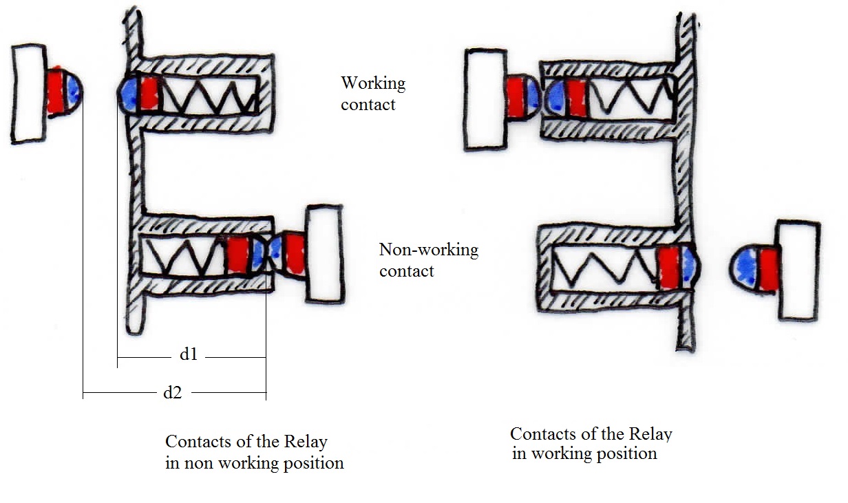
In this diagram, two distances are defined:
- d1 = nominal distance between the two movable parts of the two complementary contact elements,
- d2 = maximum distance between two stationary parts of two additional contact elements
In normal operation, the distances d1 and d2 are the same
- In case of default, the defaulting working contact (Contact welded) prevents the non working contact to change of state. Thus by reading the state of the relay contacts, it is possible to know if a contact fails.
In this case two new distances are defined:
- d3 = maximum distance between the moving parts of two complementary elements of contacts
- d4 = residual distance between the two parts of a set of contacts in the welding of a complementary contact.
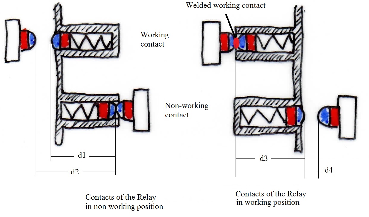
According to this standard: for a relay or contactor to be considered mechanically linked contact, in the case of welding of contacts two conditions must be met:
- first condition: complementary contacts must remain open
- second condition: the distance between the contacts (d4) must be greater than 0.5 mm for simple contacts "at openning mode"
- second condition: the distance between the contacts (d4) must be greater than 0.3 mm for the double contacts "at openning mode" through the endurance characteristics of the relay specified by the manufacturer
In addition, this type of relay must also have a certain level of reliability, since the standard specifies a minimum mechanical endurance of 107 cycles.
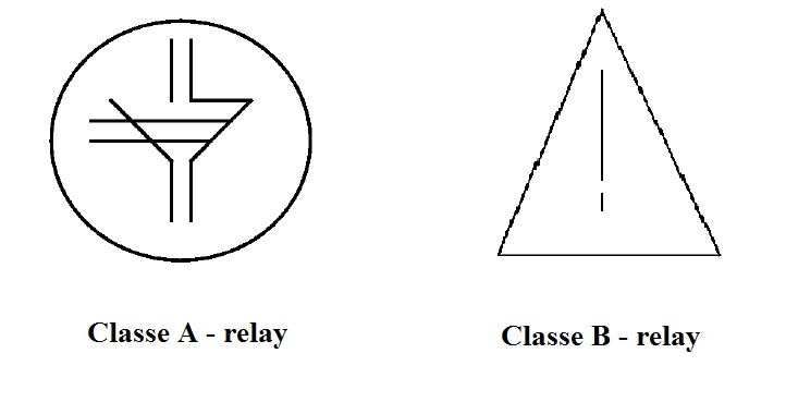
This standard also defines two classes:
- Class A were all contacts are mechanically linked
- Class B were non mechanically linked contacts can be mixed on a relay with mechanically linked contacts .
The marking on the relay is defined as follows:
English
